Suspension geometry analysis

Collapse
X
 
  • Time
  • Show
Clear All
new posts
  • chevynut
    Registered Member
    • Nov 2011
    • 11073
    • 115
    • Fort Collins, CO

    #1

    Suspension geometry analysis

    Since we have so many threads about different suspension geometries and the discussion is scattered and off-topic in a lot of them, I've started this thread to discuss the analysis of various suspension geometries and their differences. Please avoid off-topic posts here.

    I want to focus on the C4 suspensions, stock tri5 suspensions, and a stock suspension with dropped spindles or cut springs, and taller balljoints. The claim has been made in the past that a stock suspension can be made to act and perform like a C4 suspension so we've been debating that for a long time. I want to prove or dispel any statements made to that effect. Clearly the stock tri5 suspension has deficiencies and it can be made better.

    During this discussion I want to define "camber gain" as negative camber gain to avoid confusion. I want to define "spindle height" as the distance between balljoint centerlines. "A-arm length" is the distance from the center of the shaft to the center of the a-arm. A-arm "pivot" means the center of the a-arm shaft. "Level" a-arm means the a-arm pivot and balljoint are at the same height.

    Early C4 suspensions are '84-87 and late are '88-96. The suspension geometries, both front and rear, were changed in 1988. Upper and lower a-arms and spindles (knuckles) are different in the front. The late front is about 1" wider than the early front. In the rear, the location of the strut rods at the inboard attach point was lowered in 1988. All link lengths are the same in the rear, early and late. The caliper mount was changed on the late suspensions making them a bit wider. The late rear is about 1" wider than the early rear.

    To start this off, I decided to take some fairly careful measurements off of a tri5 clip I had cut off of a frame to do a C4 conversions. This allowed me to take things apart so I could take careful measurements. I even cut the balljoints apart to measure them so there would be no question of where the centers were, and it verified prior measurements.

    Here's what I found, and should be the basis for any calculations or CAD work to discuss these suspensions. If someone has what they think is better measurements, feel free to prove it.

    Stock Tri5 suspension measurements:

    Upper a-arm shaft mounting width 29 3/4" front
    Upper a-arm shaft mounting width 29" rear
    Upper a-arm shaft centerlines (no shims) 28 3/8" (average front and rear)
    Lower a-arm spacing 20 1/2"
    Vertical spacing between upper and lower a-arm shafts, 10 1/2" front, 10" rear (at upper a-arm mounting holes)
    Vertical spacing between upper and lower a-arm shafts, 10 1/4" (average at center)
    Upper to lower balljoint centers 9 3/4"
    Lower a-arm length 14 3/4"
    Upper a-arm length 10 1/4"

    Since the front and rear of the upper a-arms are not the same width or height, we should take an average of the dimensions as shown.

    So with this information, we can lay out the stock suspension and analyze it. Right off the bat we can see that with the lower a-arm level, the upper a-arm is pointing down at the outboard end and is lower than the upper a-arm pivot by 1/2". We can also see that the upper a-arm pivot is 5" outboard of the lower a-arm pivot which is further than what has previously been reported here.

    The question remains as to where "ride height" is as it pertains to a stock suspension, specifically the angle of the lower a-arm. There is a lot of information on the internet that indicates a lower a-arm should be level or slightly down at the outboard end.. The GM assembly manual shows the inner pivot to be at the same level as the lower balljoint, and with the a-arm level. Clearly to avoid tire scrub during suspension movement, the movement should center around a level a-arm. In fact, a level a-arm with some instantaneous negative camber gain would counteract that scrub as the suspension is compressed.

    I'm assuming most of the discussion will be around static geometry, but you can infer dynamic effects from that to some extent. If anyone has suspension analysis software and can participate in this discussion, that would be awesome. So let's get to it.
    Last edited by chevynut; 02-19-2016, 08:43 AM.
    56 Nomad, Ramjet 502, Viper 6-speed T56, C4 Corvette front and rear suspension


    Other vehicles:

    56 Chevy 2-door BelAir sedan
    56 Chevy 210 4-door sedan
    57 Chevy 210 4-door sedan
    1962 327/340HP Corvette
    1961 Willys CJ3B Jeep
    2001 Porsche Boxster S
    2003 Chevy Silverado 2500 HD Duramax
    2019 GMC Sierra Denali Duramax
  • chevynut
    Registered Member
    • Nov 2011
    • 11073
    • 115
    • Fort Collins, CO

    #2
    I'm copying this stuff from the other thread that got taken off-topic. I corrected this to match my new measurements so don't use the numbers in the other thread.


    .................................................. ..Tri5 ............Early C4 (84-87) .......Late C4 (88-96) ....Tri5, 1" taller balljoint
    Spindle height (balljoint centers) .... 9.75................ 11.875....................... 13.375................... 10.75
    a-arm pivot centers (vertically) ..... 10.25 .................10.84 .........................11.59 ..................10.25
    Upper a-arm length (pivot to bj) ... 10.25...................8.25 .............................8 .....................10.25
    Lower a-arm length (pivot to bj) .....14.75 .................13.25 ...........................15 ....................14.75

    The net of this is that the C4 upper a-arm balljoints are above the pivot points. With the lower a-arm level, the upper a-arm angles down toward the center of the car.
    Last edited by chevynut; 02-19-2016, 10:41 AM.
    56 Nomad, Ramjet 502, Viper 6-speed T56, C4 Corvette front and rear suspension


    Other vehicles:

    56 Chevy 2-door BelAir sedan
    56 Chevy 210 4-door sedan
    57 Chevy 210 4-door sedan
    1962 327/340HP Corvette
    1961 Willys CJ3B Jeep
    2001 Porsche Boxster S
    2003 Chevy Silverado 2500 HD Duramax
    2019 GMC Sierra Denali Duramax

    Comment

    • WagonCrazy
      Registered Member
      • Mar 2012
      • 1909
      • 530
      • Santa Clarita, CA

      #3
      Please define the years for "early C4" and "late C4". Just so we're all clear...
      1957 Nomad- LS1/T56 on C4 chassis
      1959 Fleetside Apache 1/2 ton, shortbed, big window, 327ci.

      Comment

      • chevynut
        Registered Member
        • Nov 2011
        • 11073
        • 115
        • Fort Collins, CO

        #4
        As a reminder....


        56 Nomad, Ramjet 502, Viper 6-speed T56, C4 Corvette front and rear suspension


        Other vehicles:

        56 Chevy 2-door BelAir sedan
        56 Chevy 210 4-door sedan
        57 Chevy 210 4-door sedan
        1962 327/340HP Corvette
        1961 Willys CJ3B Jeep
        2001 Porsche Boxster S
        2003 Chevy Silverado 2500 HD Duramax
        2019 GMC Sierra Denali Duramax

        Comment

        • Rick_L
          Registered Member
          • Apr 2012
          • 4676
          • 571

          #5
          I'm glad you took this discussion to its own thread. If nothing else, it will make searching for it easier in the future.

          I was hoping to discuss some things tonight, but I was unable to get a proper layout using the dimensions above. One reason I hadn't posted previously was that I was unsure of my dimensions too. So hopefully tomorrow I'm going to take some measurements on my car, compare them to those posted, and correct my layout.

          Edit: There are a couple of typos in your stock 55 dimensions. One is the average distance between the upper control arm shafts - s/b 29.375 not 28.375. Also in the dimensions for the extended ball joint, you left the spindle height stock, instead of +1".

          2nd edit: Never mind on the spindle height for the extended ball joint, I was looking in the wrong place on the chart. It's correct.
          Last edited by Rick_L; 02-18-2016, 05:39 PM.

          Comment

          • chevynut
            Registered Member
            • Nov 2011
            • 11073
            • 115
            • Fort Collins, CO

            #6
            Originally posted by Rick_L
            Edit: There are a couple of typos in your stock 55 dimensions. One is the average distance between the upper control arm shafts - s/b 29.375 not 28.375.
            Rick, the 29.375 average is surface where the a-arm shafts are attached to the frame bracket. The shafts are about 1" thick and are attached to the inside of the frame brackets, so the CENTER of the shafts is at 28.375. That's the dimension without any shims.

            Also, remember that the improvement that's supposed to "make a tri5 drive like a vette" is a 1/2" taller balljoint, not 1" . I put the 1" in the old thread to exaggerate the improvement using the taller balljoint. Let's first look at the 1/2" taller case.

            Also notice that my NEW dimension for the vertical distance between upper and lower a-arm shafts has changed sightly from what is shown in the original chart. It's actually 10 1/4" at the center of the upper shaft instead of 10". I'm going to edit that in the chart to avoid confusion.
            Last edited by chevynut; 02-19-2016, 08:55 AM.
            56 Nomad, Ramjet 502, Viper 6-speed T56, C4 Corvette front and rear suspension


            Other vehicles:

            56 Chevy 2-door BelAir sedan
            56 Chevy 210 4-door sedan
            57 Chevy 210 4-door sedan
            1962 327/340HP Corvette
            1961 Willys CJ3B Jeep
            2001 Porsche Boxster S
            2003 Chevy Silverado 2500 HD Duramax
            2019 GMC Sierra Denali Duramax

            Comment

            • chevynut
              Registered Member
              • Nov 2011
              • 11073
              • 115
              • Fort Collins, CO

              #7
              Ok I did a layout of the a-arm pivots and balljoints using the dimensions I got yesterday and something wasn't right. When laid it in CAD I got a SAI that was backwards, i.e. the steering axis is pointing inward at the bottom at about 8.5 degrees. That can't be right . The stock SAI is specified at 3 1/2 to 4 1/2 degrees. So something was wrong with one or more of the dimensions above.

              I'm pretty confident in the upper a-arm shaft mounting width (just re-checked it). I re-checked the a-arm lengths and got slightly different measurements this time. I don't know why it's so hard to measure these things, but the balljoints make it a little difficult. I used the a-arms where I removed the balljoints to measure instead of using the stud. I had cut the upper balljoint apart so it was easier to get an accurate measurement of the ball center. I also used the balljoint hole in the lower a-arm to get that length. I got 10 1/4" for the upper a-arm length, and 14 3/4" for the lower one.

              I also decided to re-measure the lower a-arm pivot width on my intact 56 sedan. I took the lower a-arms off the clip before I measured them and probably should have put them back on. I tried to estimate using the lower a-arm shaft bolts and thought that would get me close enough. This morning I measured 20.5" on my sedan, between centers of the shaft bolts by using a square from the floor to the bolt centers and marking them on the floor. Don't know how I could have been so far off. I did notice the shaft centerlines are NOT centered between the bolt holes. I corrected the post above with this new measurement. Please feel free to check any of these measurements yourself to make sure I didn't screw up.

              Using these measurements I now get a SAI of 3.39 degrees in the right direction, so these measurements look good. With a couple of shims it would be in spec. You can't do an analysis with bad dimensions . I corrected the info above again.


              Attached Files
              Last edited by chevynut; 02-19-2016, 08:50 AM.
              56 Nomad, Ramjet 502, Viper 6-speed T56, C4 Corvette front and rear suspension


              Other vehicles:

              56 Chevy 2-door BelAir sedan
              56 Chevy 210 4-door sedan
              57 Chevy 210 4-door sedan
              1962 327/340HP Corvette
              1961 Willys CJ3B Jeep
              2001 Porsche Boxster S
              2003 Chevy Silverado 2500 HD Duramax
              2019 GMC Sierra Denali Duramax

              Comment

              • Rick_L
                Registered Member
                • Apr 2012
                • 4676
                • 571

                #8
                The backward SAI was what I got when I laid out your dimensions. Also the SAI is 3.5 degrees, it is not variable. I've seen that 3.5-4.5 degrees somewhere previously, someone didn't get it. I think the layout should be done using 0 camber and 3.5 degree SAI as a starting point. Then the variable determined from the layout will be the horizontal location of the upper control arm shaft, which is more or less what it is in the real world as that's where you shim to get camber.

                I'll go back and do what I said last night, and also look at what the new info does.

                Comment

                • chevynut
                  Registered Member
                  • Nov 2011
                  • 11073
                  • 115
                  • Fort Collins, CO

                  #9
                  Here's one more piece of information on a stock suspension that may help with the analysis. The stock 6.70-15 tire rolls 755 revolutions per mile per GM 56 Chevy specs. That means the rolling radius is 13.36". Also, at stock height these are the suspension dimensions from GM. Note they show the lower a-arm level in this drawing, which may not be accurate.

                  56 Nomad, Ramjet 502, Viper 6-speed T56, C4 Corvette front and rear suspension


                  Other vehicles:

                  56 Chevy 2-door BelAir sedan
                  56 Chevy 210 4-door sedan
                  57 Chevy 210 4-door sedan
                  1962 327/340HP Corvette
                  1961 Willys CJ3B Jeep
                  2001 Porsche Boxster S
                  2003 Chevy Silverado 2500 HD Duramax
                  2019 GMC Sierra Denali Duramax

                  Comment

                  • chevynut
                    Registered Member
                    • Nov 2011
                    • 11073
                    • 115
                    • Fort Collins, CO

                    #10
                    To get more good data I've taken very careful measurements again on the C4 suspension dimensions. I actually dissected an upper balljoint to get the spindle lengths...I assumed the lower balljoint was the same length since I didn't have one to dissect. The bare spindles are 9 5/8" tall for the early suspensions, and 11 1/8" tall for the late suspensions (they're probably metric). I measured the upper balljoint center at about 1 1/8" above the spindle. I also re-measured the pivot centers as carefully as I could. The upper pivot center measurement is off of my recently assembled Nomad frame. I measured the shaft centers in front and back, and averaged them to get the center distance. The upper to lower measurement was taken off of my frame too, using the floor as the datum and measuring up to the center of the upper a-arm shaft (averaging front and rear measurements) and measuring from the floor to the lower pivot holes. I put rods across the a-arm shaft holes on an early and late k-member and found the difference in height to be exactly 3/4", which is what I measured before.
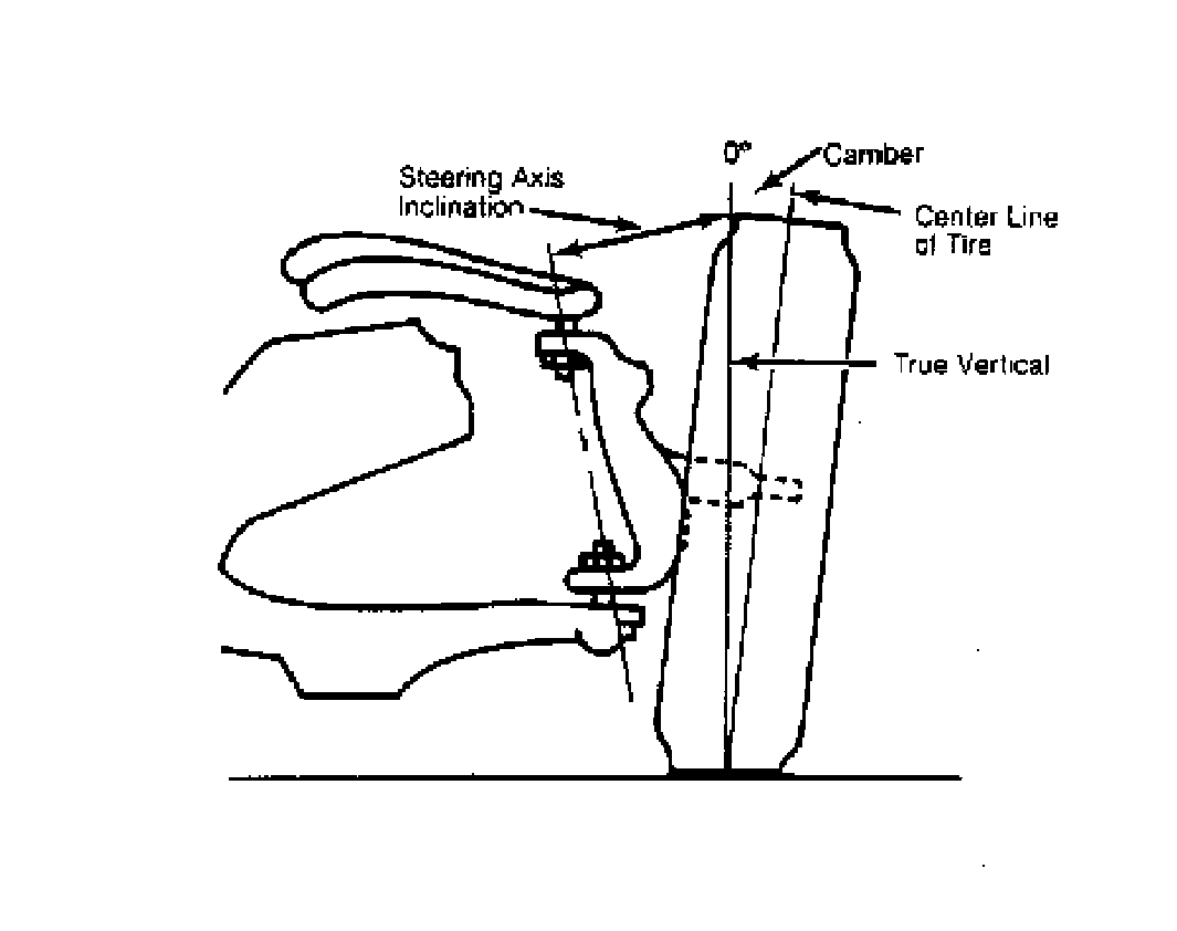
                    Here are some new measurements:

                    .................................................. ...................Early C4 ('84-87) ............Late C4 ('88-96)
                    Spindle height (@ balljoint centers) ....................... 11.875..............................13.375 (assuming 1 1/8" balljoints)
                    a-arm pivot centers (vertically) ...............................10.84 ..............................11.59 (3/4" difference in height measured)
                    Distance between upper a-arm pivots (center)..........30.00........................... ....30.00 (with 1/4" shims each side)
                    Distance between lower a-arm pivots.......................24.125............... ..............24.125
                    Upper a-arm length (pivot to bj) .............................8.25 .................................8.00
                    Lower a-arm length (pivot to bj) ............................13.25 ................................15.0

                    I corrected the table in the previous post above for these measurements to avoid confusion.
                    56 Nomad, Ramjet 502, Viper 6-speed T56, C4 Corvette front and rear suspension


                    Other vehicles:

                    56 Chevy 2-door BelAir sedan
                    56 Chevy 210 4-door sedan
                    57 Chevy 210 4-door sedan
                    1962 327/340HP Corvette
                    1961 Willys CJ3B Jeep
                    2001 Porsche Boxster S
                    2003 Chevy Silverado 2500 HD Duramax
                    2019 GMC Sierra Denali Duramax

                    Comment

                    • chevynut
                      Registered Member
                      • Nov 2011
                      • 11073
                      • 115
                      • Fort Collins, CO

                      #11
                      Rick, I got close to the right SAI with my new dimensions, mostly confirming their accuracy. It's a little less than 3.5 degrees but with a couple of shims it would be right on. Actually the SAI is variable, if you define it to the ground so maybe that's why they specify a range in the specs. Every reference I've seen for SAI shows it from "true vertical" not relative to the spindle.


                      I agree that it might be best to fix the lower a-arm, locate the upper balljoint at the 9.75" and 3.5" SAI, and then locate the upper a-arm pivot from there. That will eliminate any ambiguity regarding shims.

                      Here's where the SAI is shown as 3.5-4.5 degrees: http://chevy.oldcarmanualproject.com...esto/56031.htm
                      56 Nomad, Ramjet 502, Viper 6-speed T56, C4 Corvette front and rear suspension


                      Other vehicles:

                      56 Chevy 2-door BelAir sedan
                      56 Chevy 210 4-door sedan
                      57 Chevy 210 4-door sedan
                      1962 327/340HP Corvette
                      1961 Willys CJ3B Jeep
                      2001 Porsche Boxster S
                      2003 Chevy Silverado 2500 HD Duramax
                      2019 GMC Sierra Denali Duramax

                      Comment

                      • chevynut
                        Registered Member
                        • Nov 2011
                        • 11073
                        • 115
                        • Fort Collins, CO

                        #12
                        A little more info....from the center of the stock tri5 lower balljoint it's 2 13/16" up to the center of the spindle. Also, the tri5 wheel mounting surface is 4 7/8" outboard of the lower balljoint. The stock wheel has +9/16" offset and the front track width is 58". This with the 13.36" rolling radius will help locate the tire contact patch.

                        (edited balljoint to spindle dimension)
                        Last edited by chevynut; 02-22-2016, 09:14 AM.
                        56 Nomad, Ramjet 502, Viper 6-speed T56, C4 Corvette front and rear suspension


                        Other vehicles:

                        56 Chevy 2-door BelAir sedan
                        56 Chevy 210 4-door sedan
                        57 Chevy 210 4-door sedan
                        1962 327/340HP Corvette
                        1961 Willys CJ3B Jeep
                        2001 Porsche Boxster S
                        2003 Chevy Silverado 2500 HD Duramax
                        2019 GMC Sierra Denali Duramax

                        Comment

                        • chevynut
                          Registered Member
                          • Nov 2011
                          • 11073
                          • 115
                          • Fort Collins, CO

                          #13
                          Using all the stock measurements, here's what my CAD layout shows for a STOCK tri5 (55-56 tire dimensions) with the lower a-arm level.

                          The front suspension instant center is located 215.78" from the car's centerline on the same side as the tire in question. This puts the stock roll center at 1.61" below the ground at the center of the car.

                          My 56 sedan appears to sit at a bit higher than stock height based on the lower a-arm pivot height around 10.5". I have read that the CG should be about at the camshaft centerline, which looks to be about 20-22" above the ground on my car, as good as I can measure it. I'll call it 21" for this discussion unless someone has better data.
                          Last edited by chevynut; 02-19-2016, 12:02 PM.
                          56 Nomad, Ramjet 502, Viper 6-speed T56, C4 Corvette front and rear suspension


                          Other vehicles:

                          56 Chevy 2-door BelAir sedan
                          56 Chevy 210 4-door sedan
                          57 Chevy 210 4-door sedan
                          1962 327/340HP Corvette
                          1961 Willys CJ3B Jeep
                          2001 Porsche Boxster S
                          2003 Chevy Silverado 2500 HD Duramax
                          2019 GMC Sierra Denali Duramax

                          Comment

                          • chevynut
                            Registered Member
                            • Nov 2011
                            • 11073
                            • 115
                            • Fort Collins, CO

                            #14
                            I just looked at the scenario using a stock spindle with 1/2" taller upper balljoint, and a lower a-arm that's level, 1" and 2" above level at the lower balljoint. These are all STARTING POINTS with the camber set to zero. The car is assumed to be at ride height in each situation.

                            For the level lower a-arm, the instant center is at an infinite distance from the center of the car because the top and bottom a-arms are both level. The roll center is indeterminate (no instant center) but will be somewhere at or very slightly above ground level. I'm assuming camber is zero in this case.

                            For the 1" off-level (up) a-arm, the instant center is 341.05" from the center of the car on the opposite side of the car. The roll center is 1.05" below the ground at the center of the car.

                            For the 2" off-level (up) a-arm, the instant center is 177.26" from the center of the car on the opposite side of the car. The roll center is 1.83" below the ground at the center of the car.

                            I have not yet looked at camber curves for any of these situations.
                            56 Nomad, Ramjet 502, Viper 6-speed T56, C4 Corvette front and rear suspension


                            Other vehicles:

                            56 Chevy 2-door BelAir sedan
                            56 Chevy 210 4-door sedan
                            57 Chevy 210 4-door sedan
                            1962 327/340HP Corvette
                            1961 Willys CJ3B Jeep
                            2001 Porsche Boxster S
                            2003 Chevy Silverado 2500 HD Duramax
                            2019 GMC Sierra Denali Duramax

                            Comment

                            • Rick_L
                              Registered Member
                              • Apr 2012
                              • 4676
                              • 571

                              #15
                              Ok I've crunched several scenarios on stock based suspensions and think I've learned a bunch. I used Chevynut's latest dimensions which make sense.

                              Here's a summary of my results.

                              Roll center height
                              Stock -1.63
                              Stock w/ 2" spring drop -4.02
                              Dropped spindle -1.20
                              Extended ball joint w/ 2" spring drop -1.07
                              C3 spindle w/ 2" spring drop -0.8
                              Dropped spindle + extended ball joint 0.96

                              Roll moment arm
                              Stock 22.63
                              Stock w/ 2" spring drop 23.02
                              Dropped spindle 19.47
                              Extended ball joint w/ 2" spring drop 19.34
                              C3 spindle w/ 2" spring drop 19.07
                              Dropped spindle + extended ball joint 17.31

                              Camber gain in next 1" compression travel
                              Stock -0.21
                              Stock w/ 2" spring drop -1.00
                              Dropped spindle -0.21
                              Extended ball joint w/ 2" spring drop +0.69
                              C3 spindle w/ 2" spring drop +0.77
                              Dropped spindle + extended ball joint +0.33

                              I used Cnut's suggested 21" CG height for the initial setup, then let it move with the lowering. I think that's maybe low because what we're talking here is sprung CG not overall. Sprung is going to be a bit higher because all the unsprung is down low. But it's the same for all examples so you can see the trend.

                              Except for the stock and stock w/ 2" spring drop listing, I used the rolling radius Cnut posted for a 225/50/17 tire.

                              I think ride height could be investigated some more. I used a level lower arm for "uncut" springs.

                              I realize I should have made a table in Word or Excel and imported it, hard to read what I posted. Will do tomorrow. I've put too much time in it today already to fix it now.

                              What I see is that drop spindles get you better roll center and roll couple moment arm than other choices. The extended ball joints or C3 spindles get you more camber gain and improve the roll center a little, assuming lowering with cut springs. The combination of drop spindles and extended ball joints is an interesting mix.

                              The main benefit of the C3 spindle is the scrub radius. That and an easy way to get 12" rotors and big calipers. Otherwise the results are similar to a 1" extended ball joint, which I expected. I guess you can consider whether an extended ball joint is strong enough but it probably is.

                              As I've always said, the drawback to 2" lowering springs is the reduced travel.

                              I'm going to put mine together with the C3 spindles/brakes and see how the suspension travel deal works out, as well as seeing whether I'm happy with ride height. If I'm not satisfied, it's pretty obvious which way to go.

                              Edit: I made an attempt to make the data more readable.
                              Last edited by Rick_L; 02-20-2016, 09:07 AM.

                              Comment

                              Working...